We talk a lot about a studio’s audio chain, less about the nervous system that coordinates it. In radio as in television, that system rests largely on GPIO, for General Purpose Input/Output. It is the logic that lets a piece of audio gear trigger an event and signal another, without going through the sound signal itself.
GPIO, the language of contacts
The principle comes down to two words: input and output. An input, or GPI, waits for a contact to close in order to trigger an action inside the device. An output, or GPO, closes a contact toward the outside world to light or start something. In its historical form, all of this runs on dry contacts, that is, simple circuit closures with no imposed voltage.
Between the outside world and the device’s electronics, you almost always place a barrier: the optocoupler. This small component passes the information as light, a diode on one side, a phototransistor on the other, and galvanically isolates the two grounds. The benefit is twofold. It protects the device logic from a stray voltage, and it avoids creating a ground loop between two machines that would otherwise share a common reference point. On a set where everything is connected, that isolation is no luxury.
What it actually does
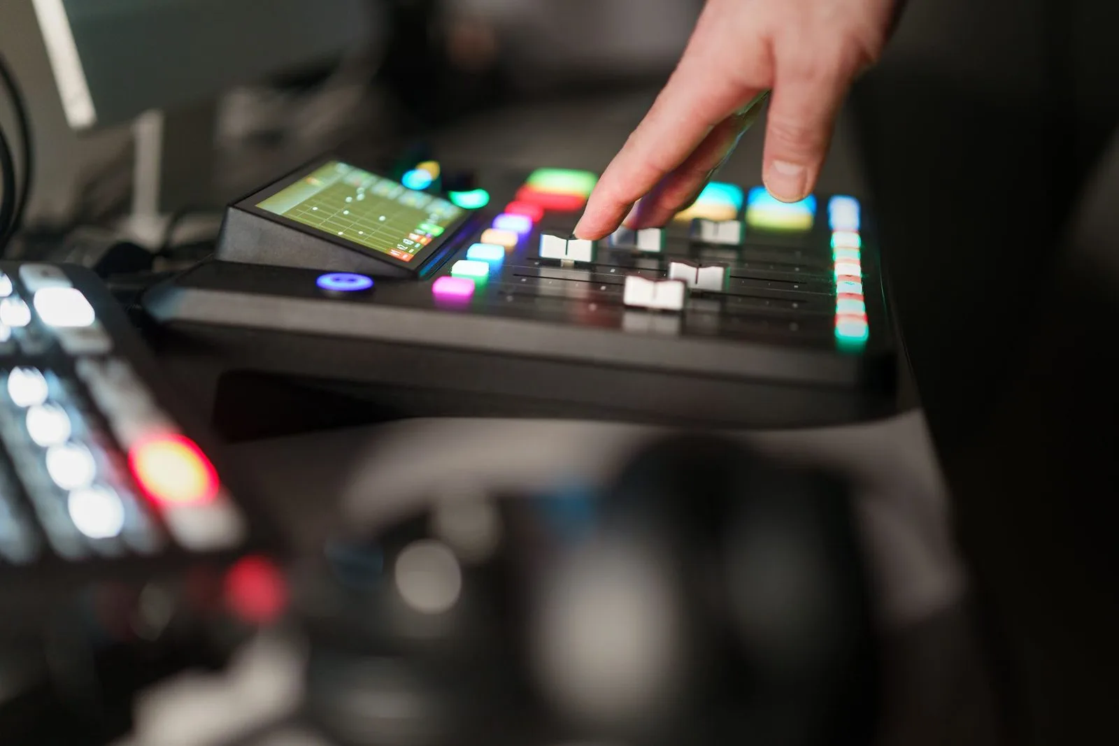
The uses are everywhere once you look at a real studio. The best known is fader start: opening a channel fader automatically fires the assigned source, cart, recorder or automation. Then comes the On Air lamp, in the studio and often in the corridor, driven by an output as soon as a mic goes live. That same open mic usually triggers the muting of the monitor speaker, to prevent any feedback.
The list goes on: the cough key that briefly mutes the mic during a cough, the tally that flags the active channel, the start of a logging recorder, or the ring and answer of a telephone hybrid. Each time, GPIO links a gesture to a consequence, with no extra human action. It is also the backbone of automated playout, as in radio automation, where logs and starts chain together on logic triggers.
From cable to network, virtual GPIO
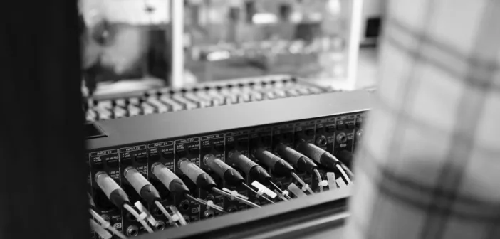
For a long time, GPIO traveled on screw terminals and multipin connectors at the back of consoles and routers. The arrival of audio over IP changed that. Control no longer needs a dedicated wire: it travels on the same network as the audio. This is what we call virtual GPIO.
Each ecosystem has its method. The Axia Livewire world carries logic through its nodes and consoles, for instance the Axia Quasar. At Lawo, the Ember+ protocol carries control states between devices, on surfaces such as the Lawo Ruby. Wheatstone does the same with its WheatNet-IP logic. The split of roles is clear: audio flows travel in AES67 or SMPTE ST 2110, while control uses these logic channels. Dante itself defines no GPIO, but many Dante-enabled devices expose controllable logic ports.
A few good habits
Three points avoid most of the trouble. First, polarity: many inputs work active-low, a contact to ground, and reversed wiring triggers nothing. Next, name and document your GPIO, or nobody will work out why a given lamp lights up six months later. Finally, for virtual GPIO, remember that the network becomes the link to look after, exactly as for audio and IP intercom: a clean addressing plan and devices in sync beat a last-minute rescue on a live night.
My take
GPIO is the job you never notice while it works, and that jumps out the day the on-air lamp stays dark. The move to virtual is a real step forward, fewer wires, more flexibility, states you can route like audio. The flip side fits in one sentence: the reliability of a dry contact was earned with a screwdriver, the reliability of GPIO over IP is earned with a network kept in order. A simple control plan and well-named channels are enough to sleep easy the night before a live show.