A mixing console reads like a subway map: lines come in on one side, connections happen in the middle, lines go out on the other. Without that map in your head, the back of a sixteen-channel desk looks like a wall of sockets. With it, every cable finds its place in seconds, and the same reasoning applies to a small analogue mixer in a bar and to a touring digital console.
This guide sets out the block diagram, walks through the inputs and outputs one by one, then applies it to three typical setups. For the cases already covered in depth — connecting a stage monitor and hooking up powered speakers — the dedicated guides take over.
Key points
- Signal travels through a console in one direction only: sources, preamps, channels, buses, outputs. Every socket on the back belongs to one of those stages.
- Pick an input by the source’s level — mic, instrument or line — and only then by the connector.
- Every destination has its own output: front of house on the master, monitors on pre-fader auxes, effects on post-fader auxes, recording on the 2-track output or USB.
- Between the console and the rest of the system, run balanced line level (XLR or TRS jack); speaker cable only comes into play after an amplifier.
The block diagram: three zones, one direction
Every console, analogue or digital, organises the signal path into three zones. On the left, the sources: microphones, instruments, players, computer. In the middle, the console itself, which brings each source up to operating level (the preamp and its gain), processes it in the channel strip (EQ, dynamics), then distributes it to buses — the master, the auxes, the groups. On the right, the destinations: front-of-house PA, stage monitors, effects, recording.
That layout has a practical consequence: no socket is there for “a bit of everything”. A mic input expects a microphone, an aux output feeds a monitor or an effect, the main output feeds front of house. Trouble starts when a socket is pressed into a job it was not designed for — a headphone output driving a speaker, a mic input taking a line-level player. The logic of buses and routing is worth understanding on its own, too: it is what makes a digital console readable.
Inputs: level first, connector second
Faced with a source, the right question is not “which socket?” but “what level?”. Three families coexist, separated by huge gaps. A microphone delivers a few millivolts; a keyboard or a professional player’s output, more than a volt. Between the two lie around fifty decibels, and bridging them is the preamp’s whole job.
| Source | Typical level | Connector | Where it goes |
|---|---|---|---|
| Dynamic microphone | Mic level, around -50 dBu | XLR | Mic input, high gain |
| Condenser mic, active DI box | Mic level | XLR | Mic input, +48 V phantom power on |
| Guitar, bass with passive pickups | Instrument level, high impedance | TS jack | Hi-Z input, or DI box then mic input |
| Keyboard, synth, professional player | Line level, +4 dBu | TRS jack or XLR | Line input |
| Computer, phone, consumer player | Line level, -10 dBV | Mini-jack, RCA, USB | Stereo input or USB channel |
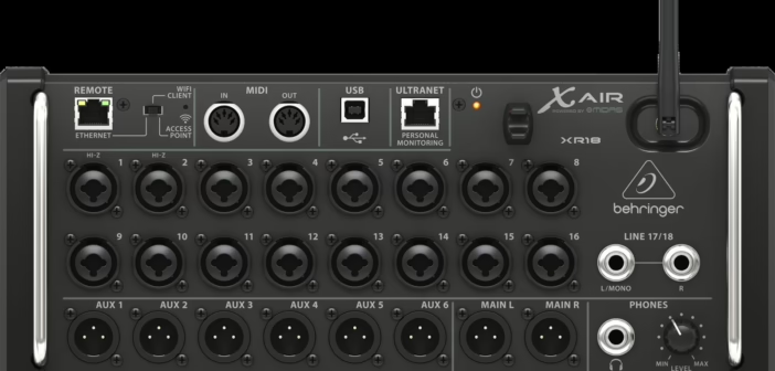
Combo inputs, which take an XLR or a jack in the same socket, muddy the waters a little: on many compact mixers the XLR feeds the mic preamp while the jack goes through an attenuator to accept line level. Hence the PAD button, an attenuation of around twenty decibels, when a line source has to go through a mic input anyway.
Guitar and bass deserve a word of their own. Passive pickups have a high output impedance and do not like an ordinary input: the sound loses its top end and its bite. Two fixes: an input marked Hi-Z or Inst, found on many compact mixers, or a DI box, which converts the signal to balanced mic level and allows a long cable run back to the desk.
Inserts and effects: the round-trip connections
Two kinds of connection are neither inputs nor outputs in the strict sense, and they are the ones that confuse people most. First, the insert: a TRS jack on the channel that sends the signal out to an external processor (compressor, EQ) and brings it back to the same point. On the vast majority of consoles, the tip carries the send and the ring the return; a Y-cable — a TRS jack on one end, two TS jacks on the other — is all it takes to patch the processor in. When in doubt, the console manual has the final word.
Then effects. An external reverb or delay is wired as a loop: an aux set to post-fader feeds the effects unit’s input, and its output comes back on a pair of line inputs or on the stereo returns provided for the purpose. Post-fader means the effect follows the source’s level: when the fader comes down, the reverb comes down with it. The difference between pre- and post-fader sends is covered in our guide to console auxiliaries.
Outputs: one destination, one output
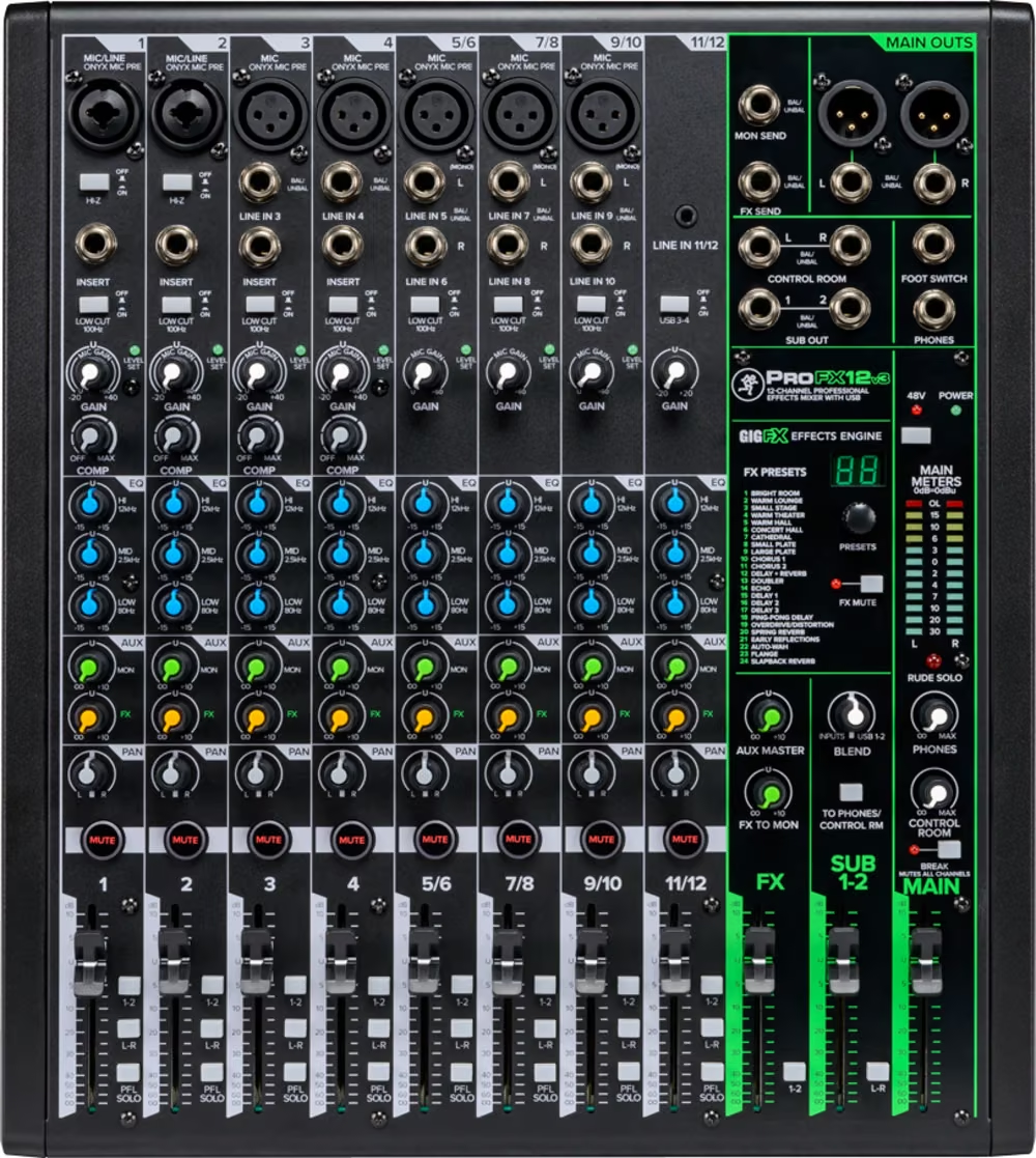
On the output side the rule is the same: each destination has its own socket, and none of them are interchangeable. The diagram below sums up the back panel of a mid-size console.
The main output (main L/R), almost always balanced XLR at line level, drives front of house: powered speakers directly, or amplifiers that power passive cabinets. Pre-fader auxes feed the stage monitors, because the band’s mix must not move when you touch up the front-of-house mix. Groups and matrices, on consoles that have them, handle secondary feeds: delay speakers at the back of the room, zones, a feed to a video truck. The 2-track output, often RCA at consumer level, and the USB port are for recording. The headphone output is for monitoring.
The headphone output is not a line output
When no output is free, it is tempting to feed a speaker or a recorder from the headphone socket. The signal there is unbalanced, its level depends on the headphone knob, and the stage is built for earphones, not for ten metres of cable. It will get you through a rehearsal; on a gig, a spare aux does the same job properly.
Three typical setups
Small PA: conference, bar, rehearsal
The most common case: two or three microphones, a computer for background music, a pair of powered speakers. The microphones go into the mic inputs over XLR, the computer into a stereo input (mini-jack to two jacks, or USB if the mixer allows it), and the main output runs over XLR to each speaker’s line input. The only trap sits on the speaker itself: its selector must be on LINE, not MIC. Levels, balancing and gain order are covered in our guide on how to connect powered speakers to a mixer. Manufacturers also publish very clear example diagrams for this kind of setup, such as Yamaha’s PA setup guides.
Live band with monitors
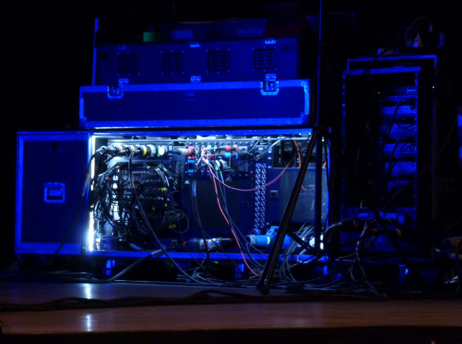
As soon as a band plays on stage, the distance between stage and desk calls for a stage box: microphones plug in at the musicians’ feet, and a multicore — one thick cable bundling several balanced pairs — runs to the console. Monitor feeds travel back down the same multicore: each pre-fader aux returns to an output on the box, which feeds a powered wedge, or an amplifier connected to a passive wedge by a Speakon speaker cable. The full mechanics of a monitor send are laid out step by step in our guide on connecting a stage monitor to a mixing console.
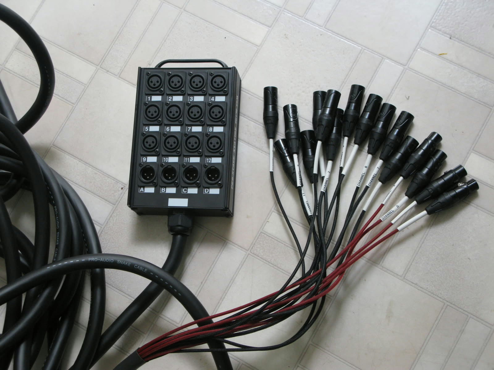
The real time-saver here is the patch list: a table that maps each source to an input number on the stage box, and therefore to a channel on the console. Kick on input 1, lead vocal on 12: when the list follows the same order everywhere, a house technician can wire the stage without you.
Digital console, network stage box and recording
In a current digital setup, the copper multicore gives way to a digital stage box: it houses the mic preamps, converts everything at the foot of the stage and talks to the console over a single network cable, using Dante, AES50 or the manufacturer’s own protocol. Monitor feeds come out of the same box. The console connects to a computer over USB or the network to record every track separately — enough to remix in peace, or to prepare a virtual soundcheck for the next show.
The cabling gets much lighter, but a new link joins the chain: the network. A damaged network cable or a badly configured switch shows up as dropouts, not as hiss. The move from analogue multicore to audio over the network is covered in our feature on patching and stage boxes in live sound.
Which cable for which connection
Five connectors cover most of a rig, each with a clear job.
- XLR: three pins, balanced. Microphones, long line runs, main outputs — the default connector as soon as there is any distance.
- TRS jack (tip, ring, sleeve): balanced for a mono line connection, but also used for inserts and headphones. Same socket, three uses: the console’s labelling is what counts.
- TS jack (tip, sleeve): unbalanced. Instruments, effects pedals, short runs.
- RCA: unbalanced, consumer level. Players, turntables after their preamp, 2-track output.
- Speakon: the power link between an amplifier and a passive cabinet, and nothing else. Its locking design and shape make it impossible to mistake for a line cable.
A balanced connection is no luxury: the signal travels on two conductors in opposite polarity, and the receiving input cancels whatever they picked up in common — hum, interference. That is what lets you run tens of metres of line cable without noise, where an unbalanced connection starts to hum beyond a few metres.
Power-up order
Amplifiers and powered speakers go on last and off first. Switching a console on while the PA is already live sends a thump through the drivers — unpleasant at best, fatal for a tweeter at worst. Faders and masters down, sources and console first, amplification after: thirty seconds of method.
When nothing comes out
If the diagram is followed and there is still no sound, the usual suspects fit in a few lines: a MIC/LINE selector in the wrong position, an aux whose master was left down, a channel not assigned to any bus, phantom power forgotten on a condenser mic. For stage monitors in particular, our step-by-step troubleshooting guide goes through faults in the order they actually turn up on stage.
On video
Soundcraft devotes an episode of its educational series to connecting equipment around a console: a good visual refresher on the block diagram.
My take
A good wiring diagram mostly spares you any thinking on show night. Once the logic clicks — sources come up to line level, buses distribute, every output has one destination and only one — any console becomes readable in two minutes, from a twelve-channel analogue desk to a digital surface. The real time-saver after that is labelling: cables tagged at both ends and a printed patch list taped to the flight case. It costs nothing, and soundcheck starts on time.