Routing has a reputation as the hard part of a digital console. It is not: it is simply taught backwards. You learn the menus of one specific machine, you memorise a sequence of gestures, and the day you change console everything has to be relearned. The underlying logic is common to every brand and comes down to one idea: a digital console separates the physical world from the logical one, and it does it twice — once on the way in, once on the way out.
- A physical input is not a channel: an input patch sits between them.
- A bus is not an output: an output patch sits between them.
- A matrix does not tap channels; it taps buses that already exist.
- The most common routing fault is double summing: a channel sent both to a group and directly to the main mix.
- A bus can clip while no individual channel is anywhere near clipping.
A digital console has three layers, not one
On an analogue console, input seven is socket seven and channel seven: the wiring is the architecture. On a digital console, the socket, the channel and the output are three independent objects joined by lookup tables you can rewrite at will. It is disorienting for the first few hours, and it is what makes the tool powerful.
Once that map is in your head the menus become readable: every page on a console deals with one of the three layers. “I/O” or “patch” pages belong to the extremities; bus, mix and matrix pages belong to the middle.
The input patch: a socket is not a channel
The stagebox numbers its sockets from one to thirty-two. Those numbers carry no authority over the console: they are cabling landmarks. The input patch decides which socket feeds which channel, and that table is free. Nothing forces you to respect the order, and nothing stops you sending the same socket to two different channels — a common technique, for instance to process a kick drum twice with two opposing EQ curves.
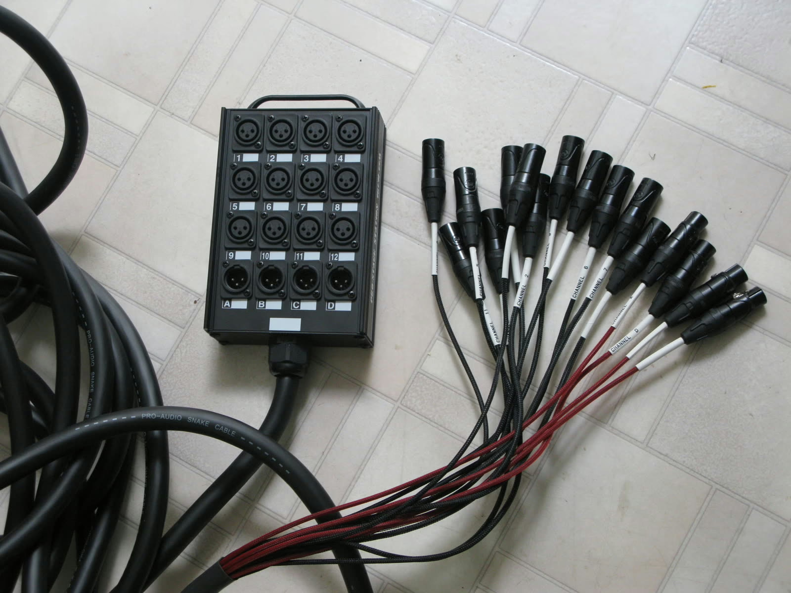
One clarification settles a lot of confusion: the preamp belongs to the socket, not to the channel. If two channels share the same physical input, they also share the analogue gain. That is what explains both how preamp sharing works between a FOH console and a monitor console on the same network, and its main constraint.
When two consoles work off the same stagebox, only one is master of the preamps. The monitor engineer who raises a gain raises it for front of house too, and the other way round. Consoles provide a digital trim per channel for exactly this, compensating locally without touching the shared preamp: that is the control to use, never the gain, once the preamp balance is locked. The protocol gets agreed before the first note, not at the first disagreement.
Buses: what each one sums, and from where
At the centre of the console, everything is a bus. A bus is a summing point: several signals arrive, add up, and leave through a single master level. What distinguishes bus types is not how they work but where they tap from.
| Object | Taps from | Used for |
|---|---|---|
| Main L/R bus | Channels, post-fader | The mix sent to the audience |
| Mix or auxiliary bus | Channels, pre or post-fader | Stage monitors, effects, zones |
| Subgroup | Channels, by direct assignment | Processing an ensemble in one move |
| Matrix | Buses that already exist, L/R included | Building a mix of mixes |
| Direct out | A single channel, no summing | Recording, feeding another console |
The tap point of mix buses — before or after the fader — is the setting that decides how they behave, and it deserves a careful read on its own: our guide to auxiliaries on an audio mixing console covers it. Note that DCAs and mute groups appear nowhere on this diagram: they carry no signal and create no bus, they only ride levels and mutes — a point developed in our article on running VCA groups.
The output patch: the last stage, and the most forgotten
A bus is not a socket. You still have to decide where it comes out, and that too is a free table. One bus can feed several outputs at once — an analogue output to an amplifier, a network channel to the recorder, a feed to the system processor — without anything duplicating the signal internally.
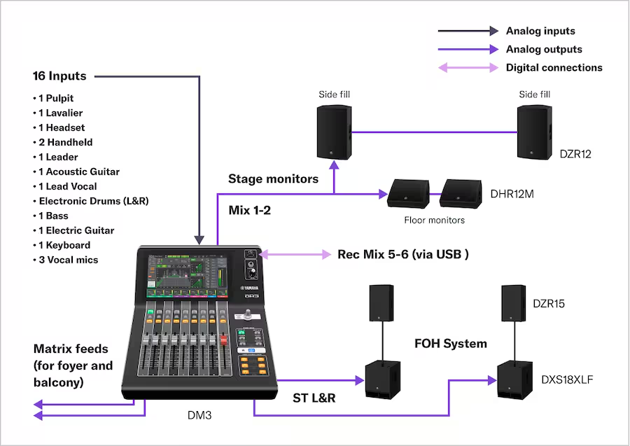
This stage settles the most concrete operational questions: which output carries the drummer’s wedge, which pair goes to the delay ring at the back of the room with its delay applied, which feed drives the video split. A manufacturer’s application diagram shows it clearly: sixteen inputs on one side, mixes heading to the stage wedges, a recording mix over USB, matrix feeds to the lobby and the balcony, and the main stereo to the house system.
Three families of architecture
Manufacturers answer the same problem in three ways, and knowing which one you have under your hands stops you hunting for a function that does not exist.
Fixed-bus architectures assign roles in advance: so many mix buses, so many subgroups, so many matrices, and you work within that split. Simple to grasp and quick to learn, at the cost of flexibility the day a stage asks for twelve monitor mixes and no subgroups.
Configurable-bus architectures offer a common pool: each bus is declared mono mix, stereo mix or group at configuration time. Far more adaptable, but it means thinking your plan through before plugging anything in — and documenting it, or nobody else will find their way around.
Architectures with a developed matrix stage, common in fixed installation and broadcast, push most of the intelligence downstream of the buses: the matrix builds the zones, the delays and the standardised feeds.
The routing faults that keep coming back
First, and by a distance the most frequent: double summing. A channel is assigned to a subgroup, the subgroup returns to the main stereo — and the channel is also still assigned directly to that stereo. The signal therefore arrives twice. The symptom is deceptive: not an obvious doubling of volume but roughly six decibels of imbalance on the affected channels only, with a slight smearing if the two paths do not carry identical latency.
Next comes invisible bus clipping. No channel is clipping, every input meter is clean, and yet the mix is hard and dirty. It is the summing that overflows: thirty correctly calibrated sources added into the same bus produce a level that bus cannot hold. The bus meters, which almost nobody looks at, say exactly that. The fix is not to pull the master fader down but to revisit gain structure upstream.
The third classic is looping: an effect return fed back into the bus feeding it, or a matrix picking up a bus it is already part of. Depending on the console this produces either outright howling or a slow, unexplained build-up. Many machines forbid the direct loop; none prevents the two-step version.
The method that solves nearly everything: follow the signal stage by stage on headphones, in pre-fader listen. Listen to the channel — the sound is there, so preamp and input patch are fine. Listen to the bus — the sound is there, so the assignment is fine. Listen to the output — the sound is gone: the problem is in the output patch. Three listens, three closed questions, and you know which layer to search instead of wandering through menus. It is also the only way to diagnose calmly while a room is waiting.
Gain is controlled at every stage, not just at the input
Gain structure is taught as a preamp matter. On a digital console it plays out in five places: the analogue preamp, the channel’s digital trim, the fader, the bus master, and finally the output gain at the patch. Each one can ruin the work of the others.
The rule that holds up over time: aim for nominal at every stage rather than compensating at the end of the chain. An output pushed to plus twelve to make up for a bus left low does work, but it leaves you no reserve and lifts the noise of everything before it.
Frequently asked questions
What is the difference between a bus and an auxiliary?
None, strictly speaking: an auxiliary is a bus. “Auxiliary” describes the use — a bus fed by channel sends to build a secondary mix — while “bus” names the object. On configurable-bus consoles, the same bus becomes an auxiliary or a subgroup depending on how you feed it.
What is a matrix?
A summing stage that taps buses rather than channels. It builds a feed out of mixes that already exist: a secondary zone, a delayed ring at the back of the room, a broadcast feed balanced differently from the house.
Can one input feed two channels?
Yes, the input patch allows it on every digital console. The two channels will share the socket’s preamp, though: only the digital trim will let you differentiate their levels.
Why does my mix clip when no channel is in the red?
Because the clipping is in the bus, not the inputs. Summing many correctly calibrated sources exceeds what the bus can hold. Look at the bus meters and revisit gain structure upstream rather than pulling the master fader down.
Subgroup or matrix for an overflow room?
A matrix, in almost every case. A subgroup works on channels and changes what goes to the house; a matrix takes the house mix as it is and lets you add or remove what is specific to that room, without altering the main mix at all.